Home
Servlet
JDBC
EJB
XML
JSP
RMI
JavaIDL
Protocols
UML
Books
UML stands for Unified Modeling Language. It is a standard language for visualizing, specifying, constructing and documenting the artifacts of a software system. It can be used throughout the software development life cycle.
Before looking into details about UML and artifacts, let us see different software development models. There are four such models.
They are:
Waterfall model consists of eight phases. They are, system feasibility, requirement analysis, product design, detailed design, development, integration, implementation and operation & maintenance. Advantages of using this model are easy to understand and adopt. The phases are completed in the natural order. Defects detected at the earlier stages are relatively cheaper to fix. The milestones and deliverables are easily understood. The disadvantages includes, there are no way to account for iteration or rework, every phase need to understood the earlier phase completely and through. The big flaw in this model is that the integration occurs at the end, this gives insufficient opportunity for the user/customer to see what he/she is going to get.
Spiral model is an elaborate from the waterfall model. Determining objectives, evaluation(prototyping), development(design, coding, testing and integration), planning the next iteration(customer evaluation, design and delivery). With its multiple builds there are several opportunities for a customer to involve in the development of the product. The disadvantages are, elaborate and hard to adopt, expensive, large number of intermediate step makes documenting and training the staff a challenge.
Rapid application development(RAD) involves analysis, design, development, and delivering to the customer. After getting the feedback from the customer the above said phases repeated with the suggestions for improvements made by the customer. And rebuilding the code continues until every body accepts the product is good enough. This is an efficient approach. Both customer and developer agrees the project completion. The disadvantage is customer always has feedback. Exit condition may never reached.
Controlled iteration is an emerging model. Rational objectory process(controlled iteration model) governs the product life from conception to completion. The life cycle consists of number of cycles, each cycle is an release. These cycles consists of four phases. They are: Inception defines the product that need to developed. Elaboration describes how the product can be developed in terms of functionality and architecture. Construction involves analysis and design. A fully functional product is developed. Transition phase involves packaging and delivering. Advantage of this process are, iterative development nature is clearly visible, phases have definite exit criteria, phases can be easily scheduled, budgeted and tracked.
Parts of UML:
Views shows different aspects of the system. There are five views:
Use-case View shows the functionality of the system as perceived by an external actor. Logical view represents the static structure(class and object diagram) and dynamic behavior(activity, state diagram, sequence diagram and collaboration diagram) of the system. Component view show the organization of the code components. Concurrency view address the problems such as concurrency and synchronization. Deployment view shows the physical architecture of nodes(computers and devices).
Diagrams are the pictorial representation of the system. There are nine diagrams in the UML. They are:
Use-case diagram shows the actors and the system. This describes the system as perceived by an external actor. Actor is external to the system being modeled. It is a user category. It can be a human or another system. This use-case diagram can be described in text. Activity diagram describes the actor use case interaction. Class diagram shows the static structure of classes in the problem domain. It represents an entity in a system. Object diagram shows the snapshot of the system including the objects and their tasks. State diagram shows the life of a single object. State is usually the value of one of the attribute. Shows the states and events that causes the state transition. Sequence diagram shows a sequence of messages between objects. Collaboration diagram also shows the message traffic between objects. A number scheme is used to show the order of the messages(calls). Component diagram shows the components in the system Deployment diagram shows the architecture of the system in terms of computers, devices and their physical distribution.
The artifacts that you can use during the life cycle are: Use-case diagram and activity diagram are drawn during the analysis phase of the software development life cycle. Use case diagram, activity diagram, class & object diagram, sequence diagram, collaboration diagram and state diagram are used during the design and development phases. Use case diagram is used in the testing phase of the system.
Use-Case Modeling
Use case modeling looks at the system from the point of view of its external users, here referred to as actors.
Purposes of use cases
- Reach agreement between customer and software developers about the functional requirements
- Provide a consistent description of what the system should do to all developers
- Provide a basis for system tests
- Provide a starting point for a trace of functional requirements to classes and operations

Actor
(Customer is the actor in the above diagram)
An actor represents a user type or category. A user that interacts with the system acts as an occurrence of this type. An actor is not part of the system itself Actors model anything that needs information exchange with the system: human users other systems hardware devices
There are sometimes reasons to distinguish between primary actors that use the system directly and secondary actors. In a ATM system, the customer is the primary actor and the bank is a secondary actor.
An active actor initiates at least on use case. A passive actor is involved in a use case, but never initiates one.
Actors can be organized in a generalization-specialization hierarchy where one actor is a more specialized case of a more general actor
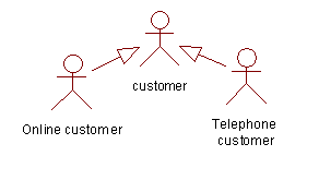
In a catalog store, customer is an actor. There can be telephone customers and online customers but they are specialized case of a customer.
Use cases
(ATM login is a use case)
Customer wants to draw money from an ATM. These are the sequence of steps he/she has to perform:
- Insert his/her ATM card
- System reads the card and prompt the user to enter the PIN
- system validates the customer and allow/disallow the user to continue

If there is a common behavior across use cases then we can avoid repeating the behavior by relating them using the include relation. In the above scenario where 'system login' includes 'identifying the customer'.

To specify that one use case is an specialization of the general use case we can use the generalization-specialization relationship
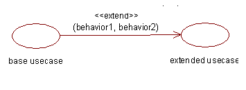
Extends is a stereotype set on the generalize specification that can be attached to a model element to give it a special meaning. Extending use case add behavior to the base use case based on condition specified in the base use case.
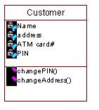
Class diagram shows the static structure of classes in the problem domain. A class represents a 'thing' or entity that is handled in the system. A system typically has a number of class diagrams. In the ATM system, customer and login window are few of the classes.
Each class is represented by a box with 3 compartments:
- name
- attributes
- operations
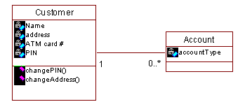
Association is a semantic relationship between two classes(for example a customer may have zero or more active accounts)
Each end of an association can have an indication of the number of objects involved in the association called multiplicity
Generalization (generalization/specialization) is a relationship between a more general class and a more specific class. It represents "is-a-kind-of" relationship between the classes(for example customer is a general class and online customer is a specialized class)

Aggregation is a particular kind of association represents a whole-part association between classes(for example a document contains pages)

Composition aggregation has "strong ownership" relation. Typically, the part class live inside the whole class. Their life times are the same: If the whole is destroyed, so are the parts. Composition aggregation is shown with a filled-in aggregation diamond

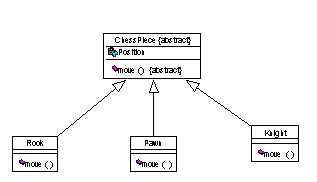
In the following diagram ChessPiece is specified as an abstract class. This let the subclass to override the move() method.
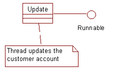
Classes can implement an interface this can be represented as
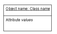
Object is represented same way as a class diagram. But it has only two compartments. The compartment for the methods is ignored.
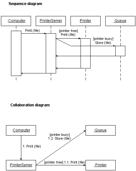
Sequence diagram shows how objects interact in a particular scenario. The vertical axis shows time, from top to bottom. The horizontal axis shows the different objects. The objectís lifeline (dashed) is connected to the object symbol. Communication is shown by means of horizontal arrows.
Collaboration diagram shows object interactions and links. While a sequence diagram focuses on time, a collaboration diagram focuses on the object 'space'. Both illustrate 'mechanisms': How objects collaborate to produce a result or achieve some other goal of the system.
more to come.....
Click on the image to order the book from Amazon.com
UML Distilled - Fowler

